
Reversing a DC Motor with two SPDT Relays
Found this on an electrical discussion forum and later in an installation manual for a linear actuator which is what I’ll be using to open and close gable vents and possibly sides of the tunnel. The set up uses two SPDT relays to reverse polarity on a DC motor so it can spin in either direction like a dordless drill.
SPDT stands for Single Pole – Double Throw. Only a Single Pole or circuit can flow through but it can go one of two ways which is the Double Throw. A Single Throw would only have the NO or Normally Open contact but Double Throw also has a NC or Normally Closed contact. Relays also have two terminals for the Coil which when energized, Throws the switch and in this case, opens the NC and closes the NO.
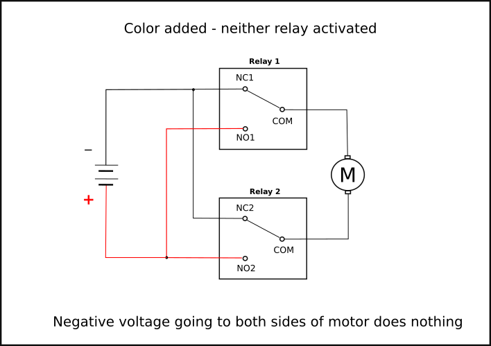
Here’s the two SPDT relay set up in a state of rest – neither relay activated.
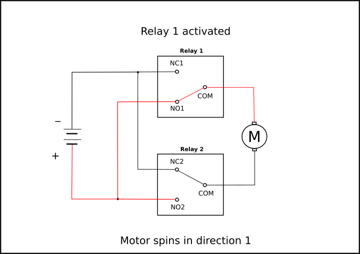
Now we make it do something by putting power to the coil on Relay 1 and the motor now has 12 vdc+ and 12 vdc- going to it and spins in direction 1
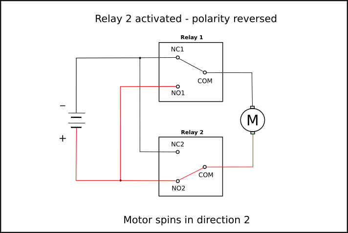
Now Relay 1 is deactivated and Relay 2 is activated and the polarity is reversed causing the motor to spin in direction 2
In the above pics, there looks to be a possibility to activate both relays and close both NO circuits which would send 12 vdc+ to both sides of the motor.
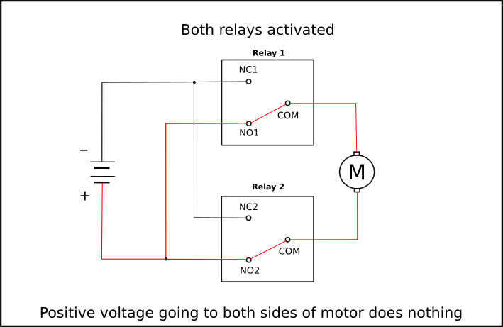
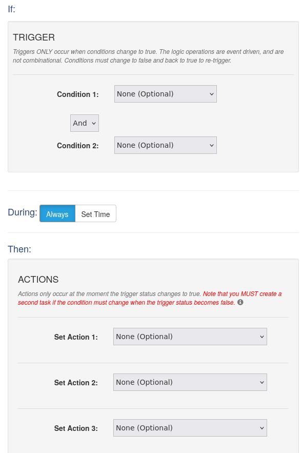
Nothing would happen because there would be no path to ground but it’s still not a desirable thing. Linear Actuators have Limit Switches that automatically cuts power when they reach either end of their stroke which helps prevent that. A simple preventative measure is for me to set a condition for activating Relay 1. (IF Relay 2 = OFF)
Let’s say Relay 1 opens the North gable vent and Relay 2 closes it. It’s morning and getting warm out there so we want to open the North gable vent. (IF temp >73 AND Relay 2 = OFF then turn Relay 1 ON) When the temp gets over 73 degrees, open the North gable vent via Relay 1 but only if the North gable vent isn’t currently closing via Relay 2. Reading it that way and it seems pretty unlikely that the North gable vent would be closing at the same time I want to open it but it’s a fail-safe.
My CBW controllers have web pages for setup, including for the conditional logic above but it has it’s limits. Two Conditions or IF statements and three Actions or LET statements
To go further, a programming language called BASIC can be used and the above IF >73 degree AND relay 2 OFF – activate relay 1 scenario would look something like this but I wouldn’t be limited to two IF statements so I could add the wind factor in there. Zero means false or off and 1 means true or on.
IF temp1 >73

AND relay2 = 0

AND Wind <25

LET relay1 = 1
Temp, relay 2 state and wind makes three and can’t be done with the set up page. The other thing that’s available only by writing BASIC scripts is the ELSE statement where I could add ELSE so if the wind is more than 35, don’t open the gable vent or only open it part way etc. It’s going to take some brain itching thought to come up with scenarios and write the code for it. I’m not a programmer but do know some basic concepts.
Meanwhile, you or I could just be standing outside and decide it’s time to close the tunnel most of the way based on various conditions, common sense and instinct. Thunder with the temperature suddenly dropping and starting to get windy, dark clouds rolling in. These controllers can’t hear thunder or see dark clouds so the best I can do is track changes in wind and temperature. How much drop in temp and increase in wind over what given length of time? Beats the hell out of me but if I was standing out in it, I’d just know based on several things and there would be no numbers or calculations involved.
Anyway, now that my brain hurts.
I’m not sure if I’ll be using automotive relays which is what the drawings are sort of based on or if I’ll use industrial relays and possibly solid state versions. Most relays are electro-mechanical devices where the coil physically moves a contact. With anything that has contacts, there is a tiny transfer of metal every time the contacts open or close. That eventually builds up and makes for poor contact. Solid State relays have no moving parts and are not mechanical, hence they last a really long time. Of course that comes with a price as they’re $30-40 each while electro-mechanical are $5-10 or so. My sides will be split in two for a total of 4 linear actuators. Two more for the gable vents makes that 6 and then I still have end doors that should open and close with the rest so make that 8 linear actuators and I need two relays per actuator for 16 relays. Solid State at $30 x 16 of them would be $480.00. Automotive relays are sounding pretty good. Rock Auto has them for $4.00 and even that’s $64.00
In either case, there are really two sets of relays involved in the above circuit. The controllers have relays but they’re not rated for many amps and are generally used to operate an external, interposer relay. My big controller has 16 relays rated for 1 amp but linear actuators and the RV pump I’m using for drip irrigation all pull more than that. The controller relays will be operating interposer relays which is what is shown in the drawings above. It takes very little power to actuate the coils which is the main purpose of having a relay. You can use very small wires and switches to run the relay coils while a heavier load can be carried through the contacts side of the relay.
Most solid state relays or even industrial relays of either type are meant for switching AC voltage even though the coils are still typically DC, most often 24 vdc which is the standard industrial control voltage. I thought about going with 24 vdc but the linear actuators are more widely available as 12 vdc and while they do make 24 vdc versions, they are expensive. Same with 24 vdc RV pumps – available but expensive.
I plan for this high tunnel to be operational during a power outage so it will have a battery bank and solar panels to charge them. I already have some 12 vdc solar panels from when we lived off grid for 5 years. Speaking of 12 vs 24 vdc, inverters for 12 vdc to 120 VAC are cheap and abundant — 24vdc, not so much. In fact, the only item that’s easier to find and no more expensive in 24 vdc is a network switch because they’re widely used in industrial control systems. Many are like my controllers that will run off of 9-28 vdc with 24vdc being preferred.
So now we have 8 linear actuators with 16 SPDT relays controlling them but only 16 SPST controller relays in my big controller. I also have a drip pump to run and possibly fans at some point. Luckily I have three Quad controllers with four SPDT relays each and they’re 2 amp each. The linear actuators pull 1.2 to 3.2 amps depending on load and the gable vents won’t be much load. I’ll figure out how to divvy them up and make it work but what about wiring and connectors? The linear actuators have five wires, two for the motor and three for the potentiometer. Potentiometer aka POT? Say what?
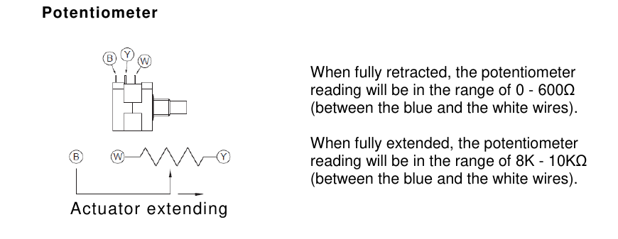
A built in potentiometer aka POT is used to determine how far extended the actuator is. It is a resistor and so you put voltage to the white and yellow wires and take a voltage reading from the blue and white wires. The controllers have a 5 vdc output to be used as a reference voltage for various things. Putting 5 vdc into the POT will return less than 1 volt when extended and between 4 and 5 volts when retracted. If it’s 0.5 to 4.5 vdc then 2.5 vdc will be 50% extended. At 1.5 vdc, it’s 75% extended which in my case, means the sides or gable vents would be 75% closed. (fully extended has the highest Ohms of resistance which means less voltage can get through, hence 1.5 vdc being mostly closed)
This means I can open/close the sides and vents how ever much I want. It’s windy enough to damage plants or catch so much wind the tunnel gets lifted and tossed across the yard but also too hot to close the tunnel all the way, close it 85%. (somewhere around 1 vdc)
But what about wiring and connectors? Wire is easy enough and I can run it in steel EMT conduit which matches the frame braces with it’s galvanized coating. With a turn down bent in all the ends, I wouldn’t even need to seal the ends, were it not for wasps and dirt dobbers.
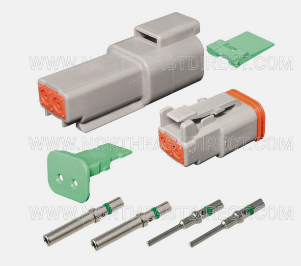
For connections, wire nuts are not meant for moist environments and would be messy. What I really need is some good weather-tight connectors like you’d find under the hood or chassis of a vehicle. You can buy the GM style but there’s a gazillion types and trying to find matches for male/female plus all the bits that make up a single connection is difficult. While searching, I ran across Deutch brand that makes connectors for aftermarket commercial truck applications. All those big trucks that come as a cab and chassis and then various companies build the bed. Fire trucks and ambulances start out as a cab and chassis as do all kinds of service trucks.
Naturally, there are Deutch knock-offs but I’ll be going with the genuine article. Here’s the two conductor version that costs $7.30 each. Yeah, twice the price of a relay. Seller give 15% discount when buying more than 4 so there is that.
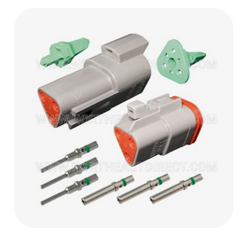
They also make 3 and 6 conductor versions for $8.25 and $11.29 respectively. Another seller based in CA has the 6 conductor at 10 for $24.95 which tells me they’re china knock offs.
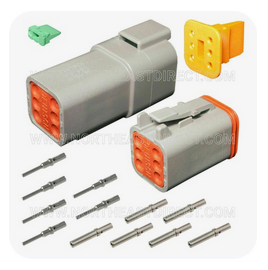
They do make plugs to seal up an unused hole in the connector so I could use a 6 way for my five wire actuators. It’s tempting to use a 2 way for the motor with 14 ga wire and a 3 way for the POT with 18 ga wires but all of the connectors will take 14, 16 or 18 ga wire so one 6 way connector per actuator would probably be the way to go. The Deutch connectors are rated for 13 amps per pin which is way more than anything in the tunnel and they’re IP67 rated (IP = Ingress Protection irrc)

I don’t live in a valley so if my tunnel is under 3 foot of water, I need to find an Ark.
Well shit, it’s almost 9am and 73 degrees, imagine that, so I better get outside and do some things before it gets hot. Some day I’ll be able to step outside about now and watch the tunnel open itself up for the day. (IF the wind isn’t 45 mph)